In plain words
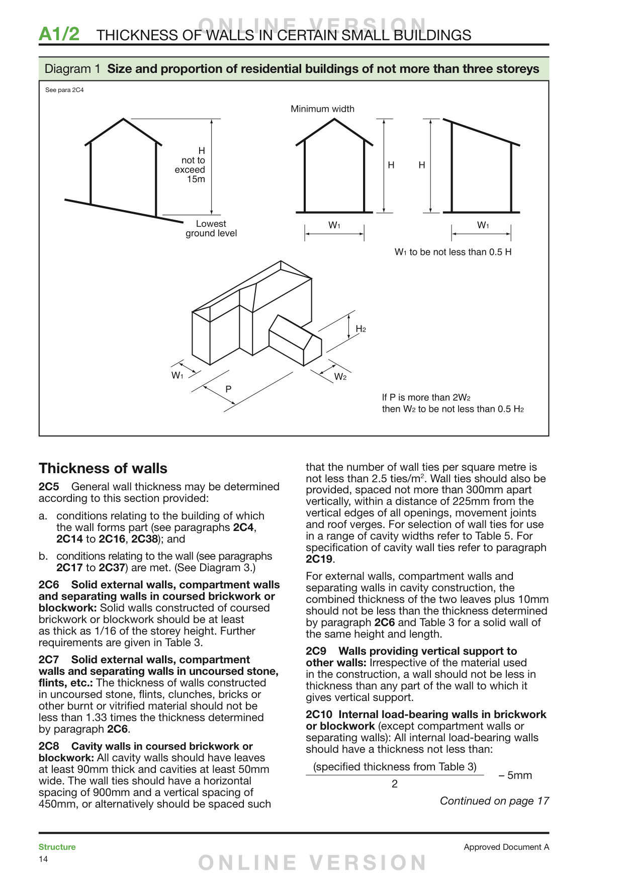
Wall thickness may be found from this section only if the conditions for the building (2C4, 2C14 to 2C16, 2C38) and for the wall (2C17 to 2C37) are met.
What it means here
Table 3 is not a free-standing rule: check the building size, floor areas, loads, openings, restraint and so on first. If any fail, the wall is outside the scope of this section (Diagram 3); in practice it then needs designing, usually by an engineer (our note).
In this build
- Use these thicknesses only if the conditions for the building and for the wall are all met (Diagram 3)Which walls Table 3 covers
In plain words
For external, compartment and separating walls built as cavity walls, the two leaves plus 10 mm should be no less than the thickness from 2C6 and Table 3 for a solid wall of the same height and length.
What it means here
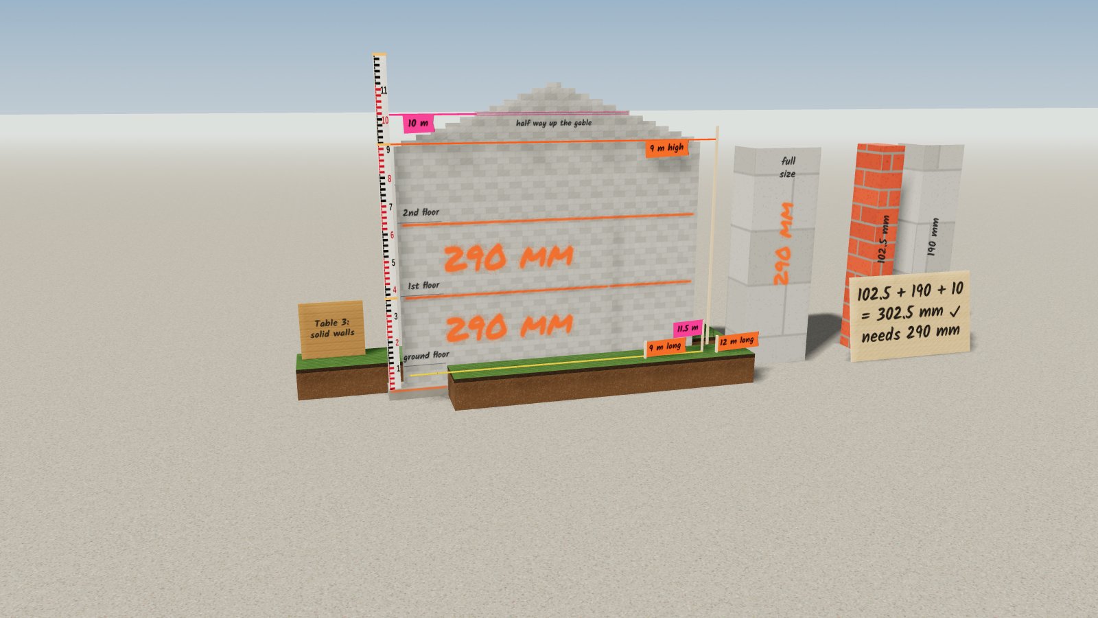
Example (ours): a 102.5 mm brick leaf and 100 mm block leaf give 212.5 mm, which beats 190 mm but not 290 mm.
In this build
- Cavity external, compartment or separating walls: the two leaves added together, plus 10 mm, must be at least the thickness 2C6 and Table 3 give for a solid wall of the same height and lengthFull size: as a cavity wall
- Each leaf at least 90 mm thick and the cavity at least 50 mm wideFull size: as a cavity wall
- Cavity external, compartment or separating walls: the two leaves added together, plus 10 mm, must be at least the thickness 2C6 and Table 3 give for a solid wall of the same height and lengthWhich walls Table 3 covers
Where it shows in the build
GableBase of wall
In plain words
Solid external, compartment (fire-separating) and separating (between homes) walls in coursed brick or block should be at least 1/16 of the storey height thick, and also meet Table 3.
What it means here
Check both and use the bigger. With 2.7 m storeys 1/16 is about 169 mm, so Table 3's 190 mm governs. A taller storey can need more: a ground storey measured from the top of the foundation (ground floor not bracing the wall) at 3.5 m needs about 219 mm; one of 3.7 m under the Diagram 8 note needs about 232 mm. The examples are ours.
In this build
- Solid walls in coursed brick or block: at least 1/16 of the storey height, and Table 3The wall
- At least 1/16 of the storey height, as well as Table 3Thickness
- Solid walls in coursed brick or block: at least 1/16 of the storey height, and Table 3Which walls Table 3 covers
In plain words
Whatever it is built of, a wall should be no thinner than any part of the wall it holds up.
What it means here
A wall can't step down in thickness and then carry a thicker wall above. Not modelled.
In this build
- A wall that holds up another wall must be at least as thick as any part of the wall it supportsWhich walls Table 3 covers
In plain words
Walls in uncoursed stone, flints, clunches, bricks or other burnt or vitrified material should be at least 1.33 times the thickness from 2C6.
What it means here
Rubble-type walls without regular courses need to be a third thicker than a coursed wall of the same storey height.
In this build
- Walls in uncoursed stone, flints and similar: at least 1.33 times the 2C6 thicknessWhich walls Table 3 covers
In plain words
Internal loadbearing walls in brick or block (other than compartment or separating walls) should be at least the Table 3 thickness divided by 2, less 5 mm.
What it means here
Where Table 3 gives 190 mm, an internal loadbearing wall needs at least 90 mm. The rest of the clause continues on page 19 (next entry).
In this build
- Internal loadbearing walls in brick or block (not compartment or separating walls): at least half the Table 3 thickness, less 5 mm. In the lowest storey of a three-storey building, carrying load from both upper storeys: that, or 140 mm, whichever is greaterWhich walls Table 3 covers
In plain words
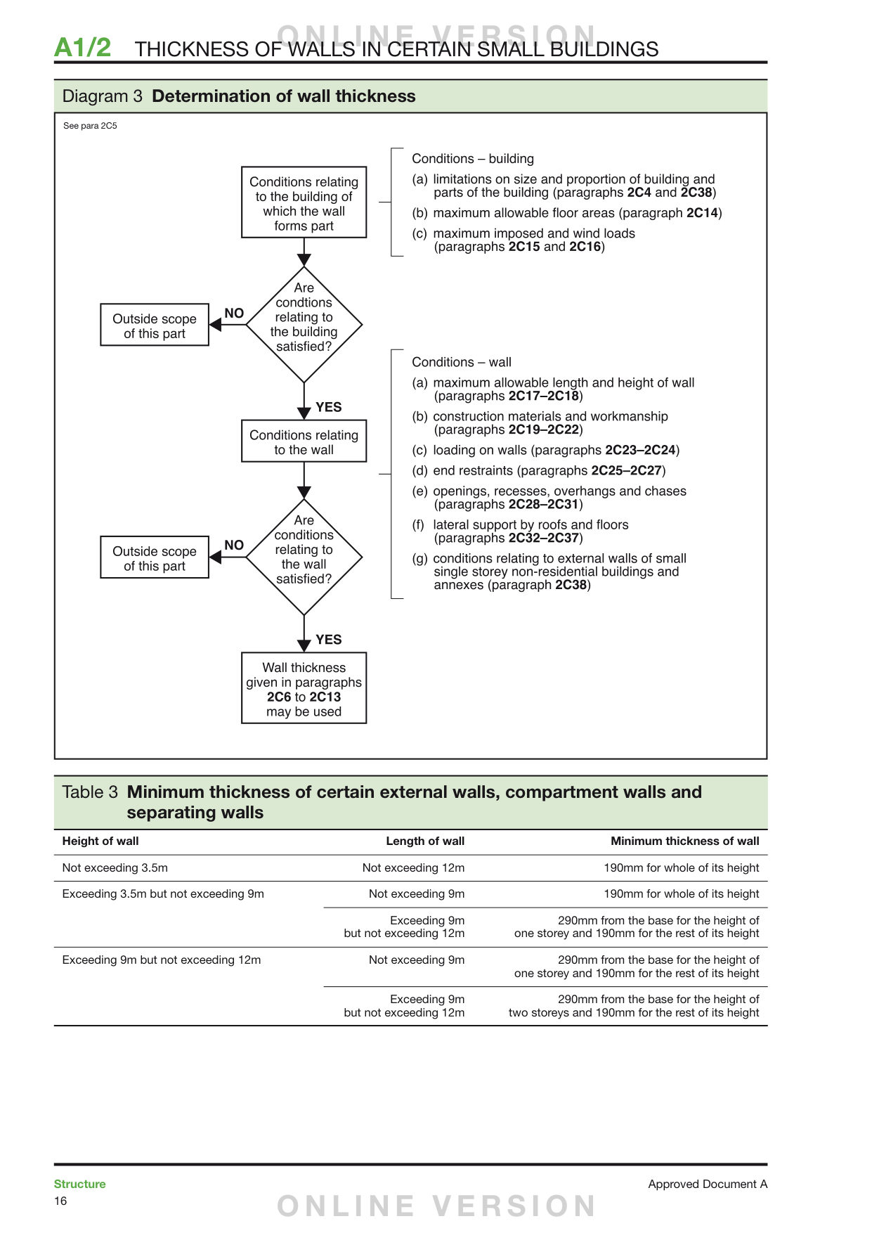
A flow chart: if the conditions for the building and then for the wall are both satisfied, wall thickness may be taken from paragraphs 2C6 to 2C13; if not, the wall is outside the scope of this part.
What it means here
The same test as 2C5, drawn as a decision chart with the list of conditions to check.
In this build
- Use these thicknesses only if the conditions for the building and for the wall are all met (Diagram 3)Which walls Table 3 covers
In plain words
Minimum thickness by wall height and length: up to 3.5 m high and up to 12 m long, 190 mm throughout; over 3.5 m up to 9 m high and up to 9 m long, 190 mm throughout; same height but over 9 m up to 12 m long, 290 mm for one storey from the base then 190 mm; over 9 m up to 12 m high and up to 9 m long, 290 mm for one storey then 190 mm; over 9 m up to 12 m high and over 9 m up to 12 m long, 290 mm for two storeys then 190 mm.
What it means here
Find the row from the wall's height and length, both measured by AD A's rules. 'Not exceeding' includes the figure itself.
In this build
- Height over 9 m up to 12 m, length up to 9 m: 290 mm from the base for the height of one storey and 190 mm for the rest of its heightFull size: solid wall
- 290 mm from the base for one or two storeys, depending on the height and length of the wall290 mm base
- At least 1/16 of the storey height, as well as Table 3Thickness
- Only walls up to 12 m high are coveredHeight H
- Only walls up to 12 m long, measured centre to centre of the buttressing walls, piers or chimneys giving restraint, are coveredLength L
In plain words
The exception: a wall in the lowest storey of a three-storey building that carries load from both upper storeys should be the thickness from the equation or 140 mm, whichever is greater.
What it means here
So a ground-floor spine wall in a three-storey house holding up both floors above needs at least 140 mm.
In this build
- Internal loadbearing walls in brick or block (not compartment or separating walls): at least half the Table 3 thickness, less 5 mm. In the lowest storey of a three-storey building, carrying load from both upper storeys: that, or 140 mm, whichever is greaterWhich walls Table 3 covers
In plain words
For bricks or blocks with modular sizes, thicknesses in this section that come from a brick or block dimension may be reduced, by no more than the size deviation a British Standard allows for equivalent units of the same material.
What it means here
A small allowance so modular units that are slightly under the nominal size still count. It does not allow a thinner wall in general.
In this build
- Modular bricks and blocks: a thickness that comes from a brick or block size may be reduced by no more than the deviation from work size that the British Standard allows for equivalent units of the same materialWhich walls Table 3 covers
In plain words
This section does not cover walls longer than 12 m, measured centre to centre of the buttressing walls, piers or chimneys that restrain them, or walls over 12 m high.
What it means here
Over 12 m in either direction, Table 3 does not apply and the wall needs engineering design (or extra buttressing walls to cut its length).
In this build
- Only walls up to 12 m high are coveredHeight H
- Only walls up to 12 m long, measured centre to centre of the buttressing walls, piers or chimneys giving restraint, are coveredLength L
In plain words
Both ends of every wall should be bonded or securely tied, for their full height, to a buttressing wall, pier or chimney (a wall or pier that braces it). Long walls may have intermediate buttressing walls, piers or chimneys splitting them into separate lengths in each storey.
What it means here
Length L in Table 3 is measured between these restraints, so adding a buttressing wall part way along can move a long wall into a thinner row.
In this build
- The ends of every wall bonded or securely tied for their full height to a buttressing wall, pier or chimney. Intermediate ones divide a long wall into separate lengthsButtressing walls (shown faint)
Where it shows in the build
Height HGableThicknessLength L
In plain words
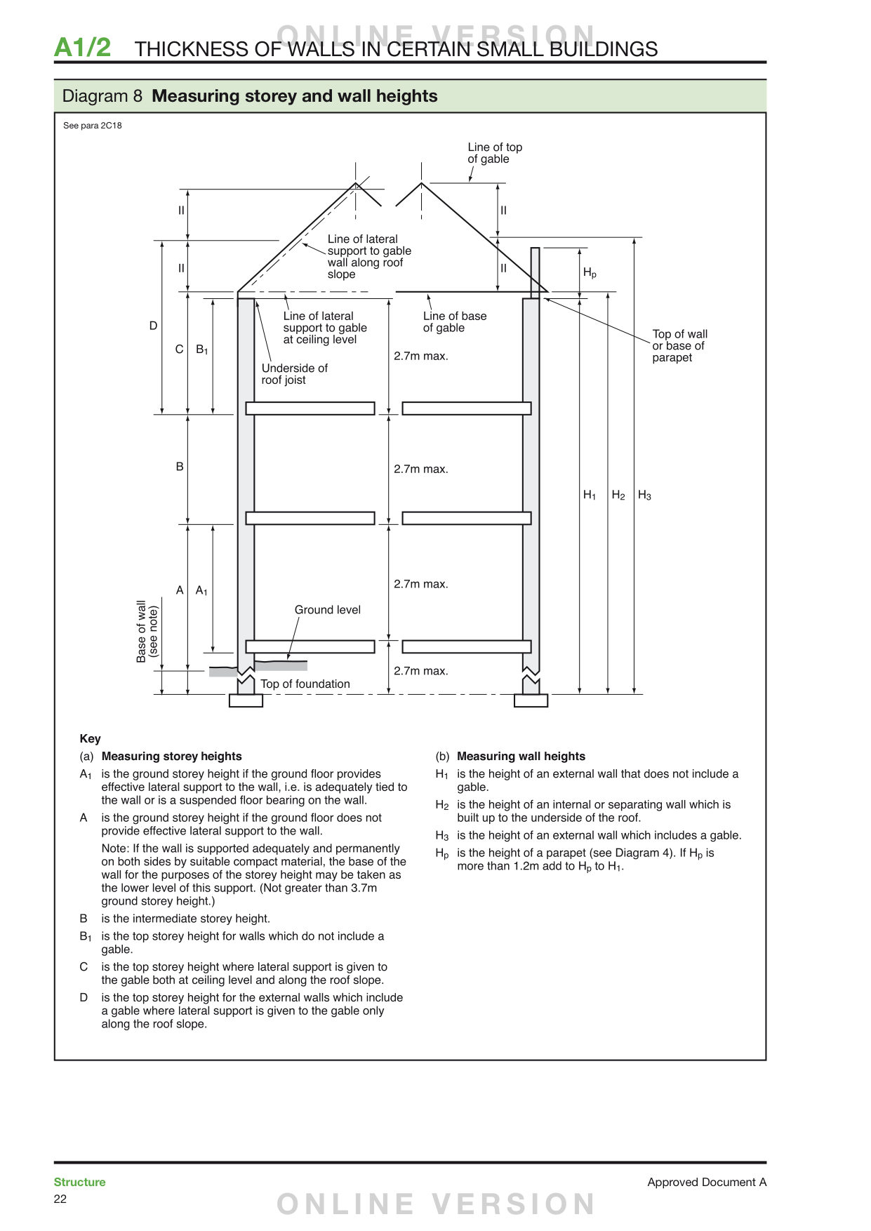
Wall and storey heights should be measured by the rules in Diagram 8.
What it means here
Heights for Table 3 are not taken from ground level by eye; follow Diagram 8.
In this build
- H3, the height of an external wall that includes a gable, measured as shown in Diagram 8: to half way up the gableGable
- Wall heights H1, H2 and H3 measured as shown in Diagram 8Height H
- Wall height is measured from the base of the wall (the top of the foundation), as shown in Diagram 8Base of wall
- Storey heights measured as shown in Diagram 8Floor levels
In plain words
Heights run from the base of the wall (top of foundation). H1: external wall with no gable, to the top of the wall or base of a parapet (a parapet over 1.2 m is added). H2: internal or separating wall, to the underside of the roof. H3: external wall with a gable, to half way up the gable (the diagram marks the two halves equal). Note: where the wall is supported on both sides by suitable compact material, the base of the wall for the ground storey height may be taken as the lower level of that support (ground storey not over 3.7 m).
What it means here
A wall is taller for Table 3 than it looks from outside, because height starts at the foundation. A gable wall is measured to half way up the gable, not to its peak. A wall over about 9 m in a house of up to three storeys is usually a gable wall; that reading is ours. Storeys of 2.7 m are the most the diagram shows.
In this build
- H3, the height of an external wall that includes a gable, measured as shown in Diagram 8: to half way up the gableGable
- Wall heights H1, H2 and H3 measured as shown in Diagram 8Height H
- Wall height is measured from the base of the wall (the top of the foundation), as shown in Diagram 8Base of wall
- Where the wall is held firmly and permanently on both sides by suitable compact fill, the ground storey height (not the wall height) may be measured from the lower of the two fill levels, as long as that storey is no more than 3.7 mBase of wall
- Storey heights measured as shown in Diagram 8Floor levels